Aircraft Pitch Control System Design and Analysis
2025, Dec 31
Project Overview: Aircraft Pitch Control System
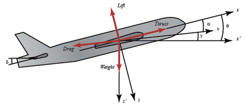
This project focuses on the modeling, stability analysis, and control system design for an aircraft’s longitudinal dynamics. The goal is to regulate the pitch angle ((\theta)) via elevator deflection ((\delta_e)) using a PID controller to ensure flight stability and precise maneuverability.
System Modeling and Properties
The aircraft’s motion is governed by linearized differential equations derived from Newton’s laws, focusing on longitudinal dynamics under steady-cruise conditions:
- Transfer Function: Open-loop dynamics modeled as a third-order system relating pitch angle to elevator input.
- Stability Analysis: Characteristic roots:
\(s = -0.3695 \pm 0.88598i, \quad s = 0\)
The root at the origin indicates marginal stability, requiring feedback control.

Methodology and Controller Design
- Design Objectives: Overshoot < 10%, rise time < 2 s, settling time < 10 s, steady-state error < 2% for a 0.2 rad step input.
- Tuning Technique: MATLAB’s Control System Designer with Root Locus and Bode plots. Balanced fast response (Response Time slider = 0.524) with robustness (Transient Behavior slider = 0.74).
Key Performance Results
- System Response: Closed-loop system stabilizes from initially unstable open-loop behavior.
- Robustness: Phase margin of 74°, ensuring stability against disturbances.
- PID Gains: Achieved target pitch with minimal overshoot and smooth settling.
Core Mathematical Framework
1. System Transfer Function
Open-loop longitudinal pitch dynamics:
\[P(s) = \frac{\Delta(s)}{\Theta(s)} = \frac{1.151 s + 0.1774}{s^3 + 0.739 s^2 + 0.9215 s}\]2. State-Space Representation
State variables: (\alpha) (angle of attack), (q) (pitch rate), (\theta) (pitch angle).
\[\begin{bmatrix} \dot{\alpha} \\ \dot{q} \\ \dot{\theta} \end{bmatrix} = \begin{bmatrix} -0.313 & 56.7 & 0 \\ -0.0139 & -0.426 & 0 \\ 0 & 56.7 & 0 \end{bmatrix} \begin{bmatrix} \alpha \\ q \\ \theta \end{bmatrix} + \begin{bmatrix} 0.232 \\ 0.0203 \\ 0 \end{bmatrix} \delta_e\]3. PID Controller Parameters
Final tuned gains:
- (K_p = 5.1504)
- (K_i = 1.74)
- (K_d = 2.908)
4. Compensator Form
The PID controller:
\[C(s) = 1.7476 \times \frac{(1 + 0.78 s)(1 + 2.2 s)}{s}\]📄 Full Project Documentation
Access the full documentation here.