Design and Analysis of a Cold Gas Rocket Engine
Project Overview
This project involves the comprehensive mathematical modeling, design, and transient performance analysis of a simplified cold gas rocket engine system.
Documentation:
View full technical report (Google Drive)
System Configuration and Specifications
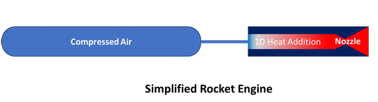
The engine model consists of three primary components designed to simulate high-performance propulsion:
- Pressurized Tank: A 0.5 m³ cold gas tank pressurized with air to an initial pressure of 200 bar.
- Combustor (Heat Addition Duct): A one-dimensional duct that simulates a combustion chamber by adding thermal energy, raising the gas temperature to a maximum of 2200 K.
- Convergent–Divergent (CD) Nozzle: A fixed-geometry nozzle designed at a 100-bar reference condition to optimize mass flow rate and expansion behavior.
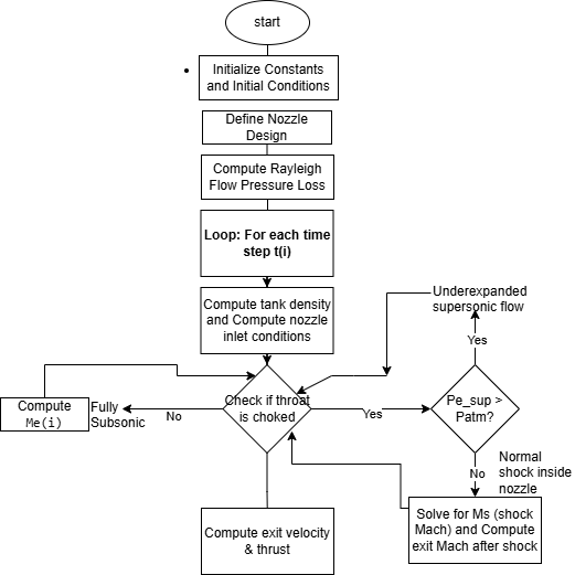
Methodology and Physical Modeling
The project utilizes an unsteady flow model based on the fundamental conservation of mass and energy. Key theoretical frameworks include:
- Isentropic Blowdown: Used to model gas depletion inside the tank, treated as a lumped control volume.
- Rayleigh Flow: Applied to estimate total pressure losses resulting from heat addition within the combustor duct.
- Shock Logic: Determines whether the nozzle operates in an underexpanded supersonic state or if a normal shock forms inside the nozzle due to pressure decay.
Key Performance Results
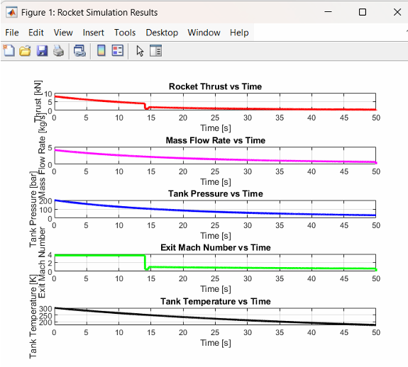
The simulation, conducted over a 50-second blowdown period, yielded the following insights:
- Thrust and Flow: Initial thrust of approximately 8.5 kN with a mass flow rate near 4 kg/s.
- Thermal Efficiency: Heat addition introduces a realistic 4.8% stagnation pressure loss, minimized by maintaining low Mach numbers (0.1–0.3) in the heating duct.
- Transient Behavior: A performance discontinuity occurs at approximately 14 seconds, marking the transition where tank pressure can no longer sustain supersonic exit flow, causing a shock to propagate into the nozzle.
- Physical Consistency: Final design results in a combustor diameter of 0.0861 m, providing a cross-sectional area approximately 5.8× larger than the throat, ensuring efficient heat addition.
Technical Implementation
The system was validated using MATLAB simulations to generate thrust–time curves and temporal profiles for tank pressure and temperature.
This analytical approach enabled a detailed understanding of how initial conditions and thermal energy addition dictate the lifecycle and propulsion performance of the engine.
Key Mathematical Frameworks
1. Isentropic Tank Blowdown
The tank is modeled as a lumped control volume undergoing an isentropic expansion. Pressure and temperature are updated at each time step based on changes in gas density:
Pressure update: \(P_{\text{tank}}^{n+1} = P_{\text{tank}}^{n} \left( \frac{\rho_{\text{new}}}{\rho_{\text{old}}} \right)^{\gamma}\)
Temperature update: \(T_{\text{tank}}^{n+1} = T_{\text{tank}}^{n} \left( \frac{\rho_{\text{new}}}{\rho_{\text{old}}} \right)^{\gamma - 1}\)
2. Nozzle Mass Flow Rate (Choked Flow)
When the nozzle operates under choked conditions, the mass flow rate is governed by the stagnation conditions and throat area:
\[\dot{m} = P_0 A^* \sqrt{ \frac{\gamma}{R T_0} \left( \frac{2}{\gamma + 1} \right)^{\frac{\gamma + 1}{\gamma - 1}} }\]where:
- $P_0$ is the stagnation pressure
- $T_0$ is the stagnation temperature
- $A^*$ is the throat area
3. Rayleigh Flow (Heat Addition)
To simulate combustion, heat is added to the flow, increasing the gas temperature to 2200 K.
This results in a loss of stagnation pressure governed by Rayleigh flow relations:
4. Normal Shock and Exit Conditions
As tank pressure decreases, the nozzle may no longer sustain supersonic flow, causing a normal shock to move inside the nozzle.
The shock Mach number is determined from the pressure balance:
\[P_{\text{sup}} \left( 1 + \frac{\gamma + 1}{2\gamma} (M_s^2 - 1) \right) = P_{\text{atm}}\]The exit Mach number after the shock is:
\[M_e = \sqrt{ \frac{\gamma M_s^2 - \frac{2}{\gamma - 1}} {1 + \frac{2}{\gamma - 1} M_s^2} }\]5. Propulsion Performance
The total thrust is calculated as the sum of momentum thrust and pressure thrust:
\[F = \dot{m} V_e + (P_e - P_{\text{atm}}) A_e\]The exit velocity is given by:
\[V_e = M_e \sqrt{\gamma R T_e}\]The exit temperature is:
\[T_e = \frac{T_0}{1 + \frac{\gamma - 1}{2} M_e^2}\]6. Combustor Geometry Design
To ensure efficient heat addition, the combustor is designed to operate at a low inlet Mach number $(M_c = 0.1)$.
The required combustor area is:
\[A_c = \frac{\dot{m} \sqrt{T_0}} {P_0} \sqrt{ \frac{R}{\gamma} } \frac{1}{M_c} \left( 1 + \frac{\gamma - 1}{2} M_c^2 \right)^{\frac{\gamma + 1}{2(\gamma - 1)}}\]The corresponding combustor diameter is:
\[D_c = \sqrt{\frac{4 A_c}{\pi}}\]